Menu
Your Cart

EV System Pro FAQs

Currently we can control any of the Cascadia PM family of inverters.

An inverter is the “controller” that takes High voltage DC power in from the battery and outputs a regulated AC voltage, the EV System Pro  VCU communicates with the inverter via CAN bus to control power delivery and implement both Performance and safety features.

Please shoot us an email at [email protected], as the VCU evolves and development continues we will make firmware available for popular applications.

A battery management system or BMS, is recommended for battery health and safety but is not required. We have used the Orion BMS2 extensively, their BMS works well and we have all the integration done into our VCU system. The Isabellenhuett IVT-S Series Smart Shunt has also been used for battery management and as an integrated current, voltage and temperature sensor in conjunction with a BMS. If you are using a BMS system not currently supported, please contact us at [email protected] and we can work to add support for your BMS system. Please note: the CAN data will be required for your BMS in order for us to implement.

Yes, We like the EMP WP32 water pumps. We can control the speed of these via CAN.

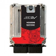
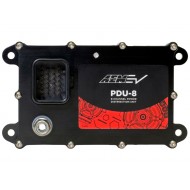
Yes, A DC-DC converter is recommended so you can use the high voltage pack to power the low voltage 12v accessories such as the AEM VCU, AEM PDU-8, and AEM CD-7. We recommend the Delphi 2.2kW DC/DC Converter. Think of this as the alternator on your ICE.

Resistor value will vary depending on the voltage level and internal capacitance of the inverter. The required value will likely be a recommendation from the inverter manufacturer. For example, the Cascadia PM250 Inverters specify a 1000- ohm pre-charge resistor with an 800v system and a 500-ohm resistor when using that same inverter with a 400v system.

Both of these units are recommended by AEM EV: ARCOL 50W Aluminum Resistors The Gigavac mini-tactor is used for the contactor that controls the pre-charge system. This is used in conjunction with the resistor.

The contactor is the high current relay that turns on /off the high voltage from the battery pack to the inverter. Gigavac are the go-to for contactors, especially the GX Series units with Aux feedback signals. The EV System Pro VCU will use this Aux feedback for confirmation that the contactor has closed. We primarily use this on the negative contactor as the positive state is inferred through the model logic.

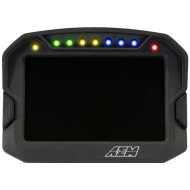
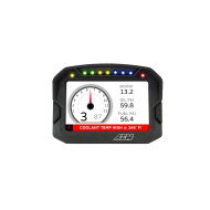
Yes the AEM CD-7 and CD-5 Digital Display units can show and log all parameters that are output by the VCU.

We have found late model Ford pedals to be the most consistent and reliable. 2016+ Mustang pedals work well. These also happen to be the same pedals Tesla uses on their vehicles. Ford Part Number: CR3Z9F836C

We like the Ford two-position brake switch from a 2016+ Mustang. These have two brake switch inputs that we use as inverse signals so that we have double confirmation signals, much like you do with a DBW Accelerator pedal. Ford Part Number: GL3Z13480A

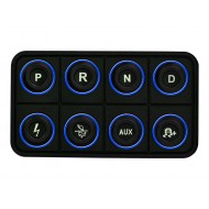
Our CAN Keypad, PN: 30-8400. Discrete inputs (switches) into the VCU may be wired directly to the VCU in the case where a keypad is not being used. The models in the VCU currently support both methods.

The VCU can select between 4 PowerMode maps for accelerator mapping, and includes user-configurable traction control. For indirect-drive applications (like a manual or automatic transmission) the VCU includes burnout control and launch control (similar to 2-step in gas-engine vehicles).

The VCU has inputs for Hall Effect Speed sensors for both driven and non-driven wheel speeds.

We have used the Thunderstruck EV J1772 connector and it's a well-made piece.

There are two channels dedicated to cooling pump on PDU-8/1 for high current pumps that require more than the 20amp max on each of those channels.

Cooling Fans can either be relay driven via low side outputs on J1-D3 & J1-D4 in the VCU200 or directly via outputs 5 and 6 in the PDU-8-1. They share the same logic and just have two outputs: CAN to PDU and direct low side out from VCU.

Since the inverter loop is critical, we recommend dedicating the VCU200s controlled loop for this. The battery is probably the 2nd most important thing to keep at a happy temp for safety reasons as well as performance. There is a temp that the battery puts out the most energy and keeping it here is critical to maximum performance and range. On the 200+ mph dragster we were involved with, we found this to be at 110F for that particular battery chemistry in that car.

We are developing firmware to allow for a PWM-based cooling pump that will use a 1D table with Temp as axis, and PWM duty as user-adjustable values. J1-K4 Wake is for CAN pumps as they require a low current 12v input to wake it up, and high-current 12v from a PDU or a relay to drive it and speed control is via CAN. This wake will not work for a PWM pump as they are usually a 3ms high PWM signal for "wake" then some duty at 150hz to control it.

A Negative Contactor is highly recommended for safety. It ensures that the battery pack is completely disconnected from the vehicle when the system is powered down. It is also a failsafe option if the system needs to be shut down, but the positive contactor is welded shut. If this occurs the VCU still can open the negative contactor since there is no possibility of it welding under normal operation, since it closes with no voltage potential across it.